-
 Agriculture
-
 Health-Care
-
 Environment
-
 Construction-Real-Estate
-
 Tools-Hardware
-
 Home-Garden
-
 Furniture
-
 Luggage-Bags-Cases
-
 Medical-devices-Supplies
-
 Gifts-Crafts
-
 Sports-Entertainment
-
 Food-Beverage
-
 Vehicles-Transportation
-
 Power-Transmission
-
 Material-Handling
-
 Renewable-Energy
-
 Safety
-
 Testing-Instrument-Equipment
-
 Construction-Building-Machinery
-
 Pet-Supplies
-
 Personal-Care-Household-Cleaning
-
 Vehicle-Accessories-Electronics-Tools
-
 School-Office-Supplies
-
 Packaging-Printing
-
 Mother-Kids-Toys
-
 Business-Services
-
 Commercial-Equipment-Machinery
-
 Apparel-Accessories
-
 Security
-
 Shoes-Accessories
-
 Vehicle-Parts-Accessories
-
 Jewelry-Eyewear-Watches-Accessories
-
 Lights-Lighting
-
 Fabric-Textile-Raw-Material
-
 Fabrication-Services
-
 Industrial-Machinery
-
 Consumer-Electronics
-
 Electrical-Equipment-Supplies
-
 Electronic-Components-Accessories-Telecommunications
-
 Home-Appliances
-
 Beauty
-
 Chemicals
-
 Rubber-Plastics
-
 Metals-Alloys
- Masonry Materials
- Curtain Walls & Accessories
- Earthwork Products
- Fireproofing Materials
- Heat Insulation Materials
- Plastic Building Materials
- Building Boards
- Soundproofing Materials
- Timber
- Waterproofing Materials
- Balustrades & Handrails
- Bathroom & Kitchen
- Flooring & Accessories
- Tiles & Accessories
- Door, Window & Accessories
- Fireplaces & Stoves
- Floor Heating Systems & Parts
- Stairs & Stair Parts
- Ceilings
- Elevators & Escalators
- Stone
- Countertops, Vanity Tops & Table Tops
- Mosaics
- Metal Building Materials
- Multifunctional Materials
- Ladders & Scaffoldings
- Mouldings
- Corner Guards
- Decorative Films
- Formwork
- Building & Industrial Glass
- Other Construction & Real Estate
- Wallpapers/Wall panels
- HVAC System & Parts
- Outdoor Facilities
- Prefabricated Buildings
- Festive & Party Supplies
- Bathroom Products
- Household Sundries
- Rain Gear
- Garden Supplies
- Household Cleaning Tools & Accessories
- Lighters & Smoking Accessories
- Home Storage & Organization
- Household Scales
- Smart Home Improvement
- Home Textiles
- Kitchenware
- Drinkware & Accessories
- Dinnerware, Coffee & Wine
- Home Decor
- Golf
- Fitness & Body Building
- Amusement Park Facilities
- Billiards, Board Game,Coin Operated Games
- Musical Instruments
- Outdoor Affordable Luxury Sports
- Camping & Hiking
- Fishing
- Sports Safety&Rehabilitation
- Ball Sports Equipments
- Water Sports
- Winter Sports
- Luxury Travel Equipments
- Sports Shoes, Bags & Accessories
- Cycling
- Other Sports & Entertainment Products
- Artificial Grass&Sports Flooring&Sports Court Equipment
- Scooters
- Food Ingredients
- Honey & Honey Products
- Snacks
- Nuts & Kernels
- Seafood
- Plant & Animal Oil
- Beverages
- Fruit & Vegetable Products
- Frog & Escargot
- Bean Products
- Egg Products
- Dairy Products
- Seasonings & Condiments
- Canned Food
- Instant Food
- Baked Goods
- Other Food & Beverage
- Meat & Poultry
- Confectionery
- Grain Products
- Feminie Care
- Hair Care & Styling
- Body Care
- Hands & Feet Care
- Hygiene Products
- Men's Grooming
- Laundry Cleaning Supplies
- Travel Size & Gift Sets
- Room Deodorizers
- Other Personal Care Products
- Pest Control Products
- Special Household Cleaning
- Floor Cleaning
- Kitchen & Bathroom Cleaning
- Oral Care
- Bath Supplies
- Yellow Pages
- Correction Supplies
- Office Binding Supplies
- Office Cutting Supplies
- Board Erasers
- Office Adhesives & Tapes
- Education Supplies
- Pencil Cases & Bags
- Notebooks & Writing Pads
- File Folder Accessories
- Calendars
- Writing Accessories
- Commercial Office Supplies
- Pencil Sharpeners
- Pens
- Letter Pad/Paper
- Paper Envelopes
- Desk Organizers
- Pencils
- Markers & Highlighters
- Filing Products
- Art Supplies
- Easels
- Badge Holder & Accessories
- Office Paper
- Printer Supplies
- Book Covers
- Other Office & School Supplies
- Stationery Set
- Boards
- Clipboards
- Stamps
- Drafting Supplies
- Stencils
- Electronic Dictionary
- Books
- Map
- Magazines
- Calculators
- Baby & Toddler Toys
- Educational Toys
- Classic Toys
- Dress Up & Pretend Play
- Toy Vehicle
- Stuffed Animals & Plush Toys
- Outdoor Toys & Structures
- Balloons & Accessories
- Baby Food
- Children's Clothing
- Baby Supplies & Products
- Maternity Clothes
- Kids Shoes
- Baby Care
- Novelty & Gag Toys
- Dolls & Accessories
- Puzzle & Games
- Blocks & Model Building Toys
- Toddler Clothing
- Baby Clothing
- Kids' Luggage & Bags
- Arts, Crafts & DIY Toys
- Action & Toy Figures
- Baby Appliances
- Hobbies & Models
- Remote Control Toys
- Promotional Toys
- Pregnancy & Maternity
- Hygiene Products
- Kid's Textile&Bedding
- Novelty & Special Use
- Toy Weapons
- Baby Gifts
- Baby Storage & Organization
- Auto Drive Systems
- ATV/UTV Parts & Accessories
- Marine Parts & Accessories
- Other Auto Parts
- Trailer Parts & Accessories
- Auto Transmission Systems
- Train Parts & Accessories
- Universal Parts
- Railway Parts & Accessories
- Auto Brake Systems
- Aviation Parts & Accessories
- Truck Parts & Accessories
- Auto Suspension Systems
- Auto Lighting Systems
- New Energy Vehicle Parts & Accessories
- Auto Steering Systems
- Wheels, Tires & Accessories
- Bus Parts & Accessories
- Auto Performance Parts
- Cooling System
- Go-Kart & Kart Racer Parts & Accessories
- Air Conditioning Systems
- Heavy Duty Vehicle Parts & Accessories
- Auto Electrical Systems
- Auto Body Systems
- Auto Engine Systems
- Container Parts & Accessories
- Motorcycle Parts & Accessories
- Refrigeration & Heat Exchange Equipment
- Machine Tool Equipment
- Food & Beverage Machinery
- Agricultural Machinery & Equipment
- Apparel & Textile Machinery
- Chemical Machinery
- Packaging Machines
- Paper Production Machinery
- Plastic & Rubber Processing Machinery
- Industrial Robots
- Electronic Products Machinery
- Metal & Metallurgy Machinery
- Woodworking Machinery
- Home Product Manufacturing Machinery
- Machinery Accessories
- Environmental Machinery
- Machinery Service
- Electrical Equipment Manufacturing Machinery
- Industrial Compressors & Parts
- Tobacco & Cigarette Machinery
- Production Line
- Used Industrial Machinery
- Electronics Production Machinery
- Other Machinery & Industrial Equipment
- Camera, Photo & Accessories
- Portable Audio, Video & Accessories
- Television, Home Audio, Video & Accessories
- Video Games & Accessories
- Mobile Phone & Accessories
- Electronic Publications
- Earphone & Headphone & Accessories
- Speakers & Accessories
- Smart Electronics
- TV Receivers & Accessories
- Mobile Phone & Computer Repair Parts
- Chargers, Batteries & Power Supplies
- Used Electronics
- VR, AR, MR Hardware & Software
- Projectors & Presentation Equipments
- Other Consumer Electronics
- Cables & Commonly Used Accessories
- Computer Hardware & Software
- Displays, Signage and Optoelectronics
- Discrete Semiconductors
- Wireless & IoT Module and Products
- Telecommunications
- Connectors, Terminals & Accessories
- Development Boards, Electronic Modules and Kits
- Circuit Protection
- Sensors
- Isolators
- Audio Components and Products
- Integrated Circuits
- Power Supplies
- Relays
- RF, Microwave and RFID
- Electronic Accessories & Supplies
- Passive Components
- PCB & PCBA
- Air Quality Appliances
- Home Appliance Parts
- Heating & Cooling Appliances
- Small Kitchen Appliances
- Laundry Appliances
- Water Heaters
- Water Treatment Appliances
- Refrigerators & Freezers
- Personal Care & Beauty Appliances
- Major Kitchen Appliances
- Cleaning Appliances
- Second-hand Appliances
- Smart Home Appliances
- Other Home Appliances
- Energy Chemicals
- Inorganic Chemicals
- Basic Organic Chemicals
- Agrochemicals
- Admixture & Additives
- Catalysts & Chemical Auxiliary Agents
- Pigments & Dyestuff
- Coating & Paint
- Daily Chemicals
- Polymer
- Organic Intermediate
- Adhesives & Sealants
- Chemical Waste
- Biological Chemical Products
- Surface Treatment Chemicals
- Painting & Coating
- Chemical Reagents
- Flavor & Fragrance
- Non-Explosive Demolition Agents
- Other Chemicals
- Custom Chemical Services
Cutting Edge High Frequency PCB Manufacturing for Military Radar Systems
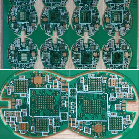
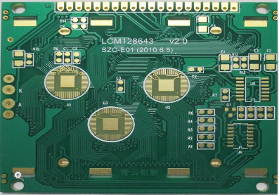
In the rapidly evolving landscape of modern defense technology, the performance of military radar systems is a critical determinant of national security. These systems, responsible for surveillance, target acquisition, and threat identification, demand unparalleled precision, reliability, and speed. At the very heart of these advanced electronic systems lies a component whose sophistication directly dictates their capability: the printed circuit board (PCB). However, these are not ordinary PCBs; they are cutting-edge, high-frequency PCBs engineered to operate at the extreme frequencies essential for modern radar applications. The manufacturing of these specialized circuits represents one of the most challenging and technologically intensive frontiers in electronics. This article delves into the intricate world of high-frequency PCB manufacturing for military radar, exploring the advanced materials, precise fabrication techniques, and rigorous testing protocols that transform complex designs into the robust, high-performance engines powering today's most critical defense systems.
Advanced Materials for Extreme Frequencies
The foundation of any high-frequency PCB is its substrate material. Standard FR-4 epoxy-glass laminates, common in consumer electronics, are wholly inadequate for military radar applications due to their significant signal loss and unstable dielectric properties at microwave frequencies. Instead, manufacturers turn to specialized high-performance materials engineered for electrical consistency and minimal loss. These include polytetrafluoroethylene (PTFE)-based substrates like Rogers RO4000 series, ceramic-filled PTFE composites, and hydrocarbon ceramic laminates.
These advanced materials are selected for their low dielectric constant (Dk) and low dissipation factor (Df). A stable Dk is crucial for maintaining consistent signal velocity and impedance control across the entire board, ensuring signal integrity. A low Df is equally important, as it minimizes the conversion of signal energy into heat, thereby reducing insertion loss. This allows radar signals to travel longer distances on the PCB without degrading, which is vital for achieving the high power and sensitivity required for long-range detection. Furthermore, these materials must exhibit exceptional thermal stability to withstand the wide temperature fluctuations encountered in military environments, from desert heat to high-altitude cold, without compromising their electrical characteristics.
Precision Design and Fabrication Techniques
The transition from material selection to a functional PCB requires an extraordinary level of precision in both design and fabrication. The design phase heavily relies on sophisticated electromagnetic (EM) simulation software. Engineers use these tools to model signal behavior, optimize trace geometries, and control impedance with tolerances often tighter than ±5%. Critical aspects include the design of microstrip and stripline transmission lines, careful via structuring to minimize parasitic inductance and capacitance, and the implementation of grounding strategies that prevent unwanted radiation and coupling.
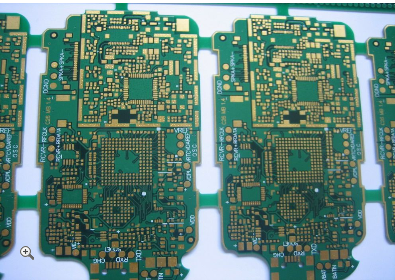
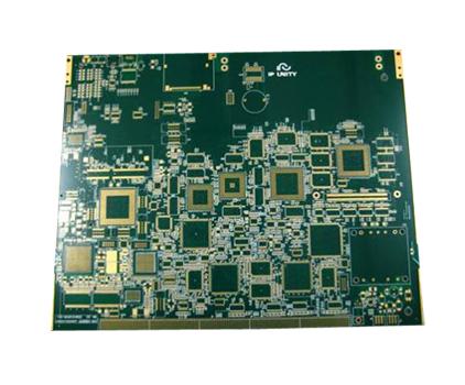
During fabrication, this design precision must be physically realized. This demands state-of-the-art processes such as laser direct imaging (LDI) for creating photomasks, which provides superior resolution for fine lines and spaces. Controlled impedance machining is used to etch copper traces to exacting widths. For multilayer boards, which are standard in complex radar systems, the lamination process must be meticulously controlled to prevent voids and ensure perfect layer-to-layer registration. Any misalignment can lead to impedance discontinuities, causing signal reflections and degrading radar performance. Plated through-holes (PTHs) and blind/buried vias are fabricated with high aspect ratios to ensure reliable interconnects between layers, even in thick, multi-layered assemblies.
Stringent Quality Control and Reliability Testing
Given the mission-critical nature of military radar systems, quality control is not merely a step in the process; it is an integral part of the manufacturing philosophy. Every high-frequency PCB undergoes a battery of rigorous tests to verify its performance and long-term reliability. Non-destructive testing methods, such as automated optical inspection (AOI) and X-ray inspection, are used to check for defects like shorts, opens, and layer misregistration that are invisible to the naked eye.
Electrical testing is paramount. This includes time-domain reflectometry (TDR) to precisely measure characteristic impedance and identify any discontinuities along transmission lines. Network analyzer testing is conducted to measure scattering parameters (S-parameters), such as insertion loss and return loss, across the entire operational frequency band. These tests validate that the PCB meets its specified high-frequency performance criteria. Beyond electrical performance, the boards are subjected to environmental stress tests—including thermal cycling, humidity exposure, and vibration tests—to ensure they can endure the harsh conditions of military deployment without failure.
Conclusion and Future Outlook
The manufacturing of cutting-edge high-frequency PCBs is a discipline that sits at the intersection of materials science, precision engineering, and rigorous quality assurance. It is a field defined by its uncompromising standards, where every micron of tolerance and every fraction of a decibel in signal loss carries significant weight. The resulting PCBs are not just components; they are the enabling technology that allows military radar systems to achieve unprecedented levels of resolution, range, and reliability.
Looking ahead, the demands on this technology will only intensify. The advent of new radar paradigms, such as Active Electronically Scanned Array (AESA) radars, which comprise thousands of individual transmit/receive modules, requires even higher levels of integration and performance from PCBs. Future advancements will likely involve the adoption of even lower-loss materials, the integration of embedded active and passive components within the PCB substrate itself, and the exploration of novel architectures like additive manufacturing for creating three-dimensional circuit structures. As radar technology continues to evolve, the innovation in high-frequency PCB manufacturing will remain a cornerstone of military electronic superiority.
REPORT


