







-
 Agriculture
-
 Health-Care
-
 Environment
-
 Construction-Real-Estate
-
 Tools-Hardware
-
 Home-Garden
-
 Furniture
-
 Luggage-Bags-Cases
-
 Medical-devices-Supplies
-
 Gifts-Crafts
-
 Sports-Entertainment
-
 Food-Beverage
-
 Vehicles-Transportation
-
 Power-Transmission
-
 Material-Handling
-
 Renewable-Energy
-
 Safety
-
 Testing-Instrument-Equipment
-
 Construction-Building-Machinery
-
 Pet-Supplies
-
 Personal-Care-Household-Cleaning
-
 Vehicle-Accessories-Electronics-Tools
-
 School-Office-Supplies
-
 Packaging-Printing
-
 Mother-Kids-Toys
-
 Business-Services
-
 Commercial-Equipment-Machinery
-
 Apparel-Accessories
-
 Security
-
 Shoes-Accessories
-
 Vehicle-Parts-Accessories
-
 Jewelry-Eyewear-Watches-Accessories
-
 Lights-Lighting
-
 Fabric-Textile-Raw-Material
-
 Fabrication-Services
-
 Industrial-Machinery
-
 Consumer-Electronics
-
 Electrical-Equipment-Supplies
-
 Electronic-Components-Accessories-Telecommunications
-
 Home-Appliances
-
 Beauty
-
 Chemicals
-
 Rubber-Plastics
-
 Metals-Alloys







































































































































































































































































































































































- Masonry Materials
- Curtain Walls & Accessories
- Earthwork Products
- Fireproofing Materials
- Heat Insulation Materials
- Plastic Building Materials
- Building Boards
- Soundproofing Materials
- Timber
- Waterproofing Materials
- Balustrades & Handrails
- Bathroom & Kitchen
- Flooring & Accessories
- Tiles & Accessories
- Door, Window & Accessories
- Fireplaces & Stoves
- Floor Heating Systems & Parts
- Stairs & Stair Parts
- Ceilings
- Elevators & Escalators
- Stone
- Countertops, Vanity Tops & Table Tops
- Mosaics
- Metal Building Materials
- Multifunctional Materials
- Ladders & Scaffoldings
- Mouldings
- Corner Guards
- Decorative Films
- Formwork
- Building & Industrial Glass
- Other Construction & Real Estate
- Wallpapers/Wall panels
- HVAC System & Parts
- Outdoor Facilities
- Prefabricated Buildings
- Festive & Party Supplies
- Bathroom Products
- Household Sundries
- Rain Gear
- Garden Supplies
- Household Cleaning Tools & Accessories
- Lighters & Smoking Accessories
- Home Storage & Organization
- Household Scales
- Smart Home Improvement
- Home Textiles
- Kitchenware
- Drinkware & Accessories
- Dinnerware, Coffee & Wine
- Home Decor
- Golf
- Fitness & Body Building
- Amusement Park Facilities
- Billiards, Board Game,Coin Operated Games
- Musical Instruments
- Outdoor Affordable Luxury Sports
- Camping & Hiking
- Fishing
- Sports Safety&Rehabilitation
- Ball Sports Equipments
- Water Sports
- Winter Sports
- Luxury Travel Equipments
- Sports Shoes, Bags & Accessories
- Cycling
- Other Sports & Entertainment Products
- Artificial Grass&Sports Flooring&Sports Court Equipment
- Scooters
- Food Ingredients
- Honey & Honey Products
- Snacks
- Nuts & Kernels
- Seafood
- Plant & Animal Oil
- Beverages
- Fruit & Vegetable Products
- Frog & Escargot
- Bean Products
- Egg Products
- Dairy Products
- Seasonings & Condiments
- Canned Food
- Instant Food
- Baked Goods
- Other Food & Beverage
- Meat & Poultry
- Confectionery
- Grain Products
- Feminie Care
- Hair Care & Styling
- Body Care
- Hands & Feet Care
- Hygiene Products
- Men's Grooming
- Laundry Cleaning Supplies
- Travel Size & Gift Sets
- Room Deodorizers
- Other Personal Care Products
- Pest Control Products
- Special Household Cleaning
- Floor Cleaning
- Kitchen & Bathroom Cleaning
- Oral Care
- Bath Supplies
- Yellow Pages
- Correction Supplies
- Office Binding Supplies
- Office Cutting Supplies
- Board Erasers
- Office Adhesives & Tapes
- Education Supplies
- Pencil Cases & Bags
- Notebooks & Writing Pads
- File Folder Accessories
- Calendars
- Writing Accessories
- Commercial Office Supplies
- Pencil Sharpeners
- Pens
- Letter Pad/Paper
- Paper Envelopes
- Desk Organizers
- Pencils
- Markers & Highlighters
- Filing Products
- Art Supplies
- Easels
- Badge Holder & Accessories
- Office Paper
- Printer Supplies
- Book Covers
- Other Office & School Supplies
- Stationery Set
- Boards
- Clipboards
- Stamps
- Drafting Supplies
- Stencils
- Electronic Dictionary
- Books
- Map
- Magazines
- Calculators
- Baby & Toddler Toys
- Educational Toys
- Classic Toys
- Dress Up & Pretend Play
- Toy Vehicle
- Stuffed Animals & Plush Toys
- Outdoor Toys & Structures
- Balloons & Accessories
- Baby Food
- Children's Clothing
- Baby Supplies & Products
- Maternity Clothes
- Kids Shoes
- Baby Care
- Novelty & Gag Toys
- Dolls & Accessories
- Puzzle & Games
- Blocks & Model Building Toys
- Toddler Clothing
- Baby Clothing
- Kids' Luggage & Bags
- Arts, Crafts & DIY Toys
- Action & Toy Figures
- Baby Appliances
- Hobbies & Models
- Remote Control Toys
- Promotional Toys
- Pregnancy & Maternity
- Hygiene Products
- Kid's Textile&Bedding
- Novelty & Special Use
- Toy Weapons
- Baby Gifts
- Baby Storage & Organization
- Auto Drive Systems
- ATV/UTV Parts & Accessories
- Marine Parts & Accessories
- Other Auto Parts
- Trailer Parts & Accessories
- Auto Transmission Systems
- Train Parts & Accessories
- Universal Parts
- Railway Parts & Accessories
- Auto Brake Systems
- Aviation Parts & Accessories
- Truck Parts & Accessories
- Auto Suspension Systems
- Auto Lighting Systems
- New Energy Vehicle Parts & Accessories
- Auto Steering Systems
- Wheels, Tires & Accessories
- Bus Parts & Accessories
- Auto Performance Parts
- Cooling System
- Go-Kart & Kart Racer Parts & Accessories
- Air Conditioning Systems
- Heavy Duty Vehicle Parts & Accessories
- Auto Electrical Systems
- Auto Body Systems
- Auto Engine Systems
- Container Parts & Accessories
- Motorcycle Parts & Accessories
- Refrigeration & Heat Exchange Equipment
- Machine Tool Equipment
- Food & Beverage Machinery
- Agricultural Machinery & Equipment
- Apparel & Textile Machinery
- Chemical Machinery
- Packaging Machines
- Paper Production Machinery
- Plastic & Rubber Processing Machinery
- Industrial Robots
- Electronic Products Machinery
- Metal & Metallurgy Machinery
- Woodworking Machinery
- Home Product Manufacturing Machinery
- Machinery Accessories
- Environmental Machinery
- Machinery Service
- Electrical Equipment Manufacturing Machinery
- Industrial Compressors & Parts
- Tobacco & Cigarette Machinery
- Production Line
- Used Industrial Machinery
- Electronics Production Machinery
- Other Machinery & Industrial Equipment
- Camera, Photo & Accessories
- Portable Audio, Video & Accessories
- Television, Home Audio, Video & Accessories
- Video Games & Accessories
- Mobile Phone & Accessories
- Electronic Publications
- Earphone & Headphone & Accessories
- Speakers & Accessories
- Smart Electronics
- TV Receivers & Accessories
- Mobile Phone & Computer Repair Parts
- Chargers, Batteries & Power Supplies
- Used Electronics
- VR, AR, MR Hardware & Software
- Projectors & Presentation Equipments
- Other Consumer Electronics
- Cables & Commonly Used Accessories
- Computer Hardware & Software
- Displays, Signage and Optoelectronics
- Discrete Semiconductors
- Wireless & IoT Module and Products
- Telecommunications
- Connectors, Terminals & Accessories
- Development Boards, Electronic Modules and Kits
- Circuit Protection
- Sensors
- Isolators
- Audio Components and Products
- Integrated Circuits
- Power Supplies
- Relays
- RF, Microwave and RFID
- Electronic Accessories & Supplies
- Passive Components
- PCB & PCBA
- Air Quality Appliances
- Home Appliance Parts
- Heating & Cooling Appliances
- Small Kitchen Appliances
- Laundry Appliances
- Water Heaters
- Water Treatment Appliances
- Refrigerators & Freezers
- Personal Care & Beauty Appliances
- Major Kitchen Appliances
- Cleaning Appliances
- Second-hand Appliances
- Smart Home Appliances
- Other Home Appliances
- Energy Chemicals
- Inorganic Chemicals
- Basic Organic Chemicals
- Agrochemicals
- Admixture & Additives
- Catalysts & Chemical Auxiliary Agents
- Pigments & Dyestuff
- Coating & Paint
- Daily Chemicals
- Polymer
- Organic Intermediate
- Adhesives & Sealants
- Chemical Waste
- Biological Chemical Products
- Surface Treatment Chemicals
- Painting & Coating
- Chemical Reagents
- Flavor & Fragrance
- Non-Explosive Demolition Agents
- Other Chemicals
- Custom Chemical Services

How to Define Material Boundaries and Color Zones in Custom Double Shot Molding Parts
A clear double shot molding specification should show every material boundary, color zone, and transition directly on the 2D drawing or 3D model. Divide the component into Shot 1 and Shot 2, assign the correct material and color to each area, and describe whether the interface is sharp, blended, overmolded, or concealed. Include surface finish, dimensional tolerances, inspection locations, and sample approval requirements so the tooling and production teams share the same visual and technical reference.
Essential Drawing Information
Begin by separating the product geometry into clearly identified shot regions. Each region should include its material designation, color reference, functional purpose, cosmetic classification, and any surfaces that must remain free of flash, sink marks, or color contamination.
- Label the first and second molded areas as Shot 1 and Shot 2.
- Assign a material, color standard, and functional role to every zone.
- Indicate whether each interface is fixed, blended, overlapping, or formed by overmolding.
- Identify cosmetic surfaces, critical dimensions, finish requirements, and inspection points.
- Use an approved sample to establish the final appearance when color names alone are insufficient.
How to Show Boundaries and Transitions
A visible and fixed interface should be represented by a continuous boundary line on the drawing or model. Where the second material covers a base section, show the underlying geometry and define the required coverage, thickness, or overlap when these values are controlled by the design.
Hidden, curved, or difficult-to-inspect interfaces require additional documentation. A sectional view, enlarged detail, or 3D annotation can reveal the intended transition and prevent the mold maker from interpreting the boundary from color alone. The drawing should also distinguish a clean color separation from a controlled blend or a concealed mechanical connection.
Color and Surface Requirements
Every color zone should have an identifiable color reference and a clear indication of which surfaces are visible to the customer. Specify the required SPI or VDI texture for each cosmetic region, together with limits for mismatch, flash, gate marks, and color migration where applicable.
For appearance-critical parts, the approved trial sample should be treated as the visual benchmark. This helps production teams evaluate color position, boundary alignment, texture consistency, and overall surface quality in addition to dimensional compliance.
Tooling and Inspection Considerations
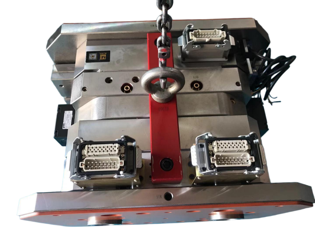
Longterm Mold provides custom precision plastic injection molds, including single-cavity, multi-cavity, double shot, and overmolding solutions. Available options include hot runners and SPI or VDI surface finishes, while stated mold service life ranges from 50,000 to 1,000,000 shots. These capabilities allow the specified color layout and material interface to be connected with cavity design, gating, surface treatment, and expected production volume.
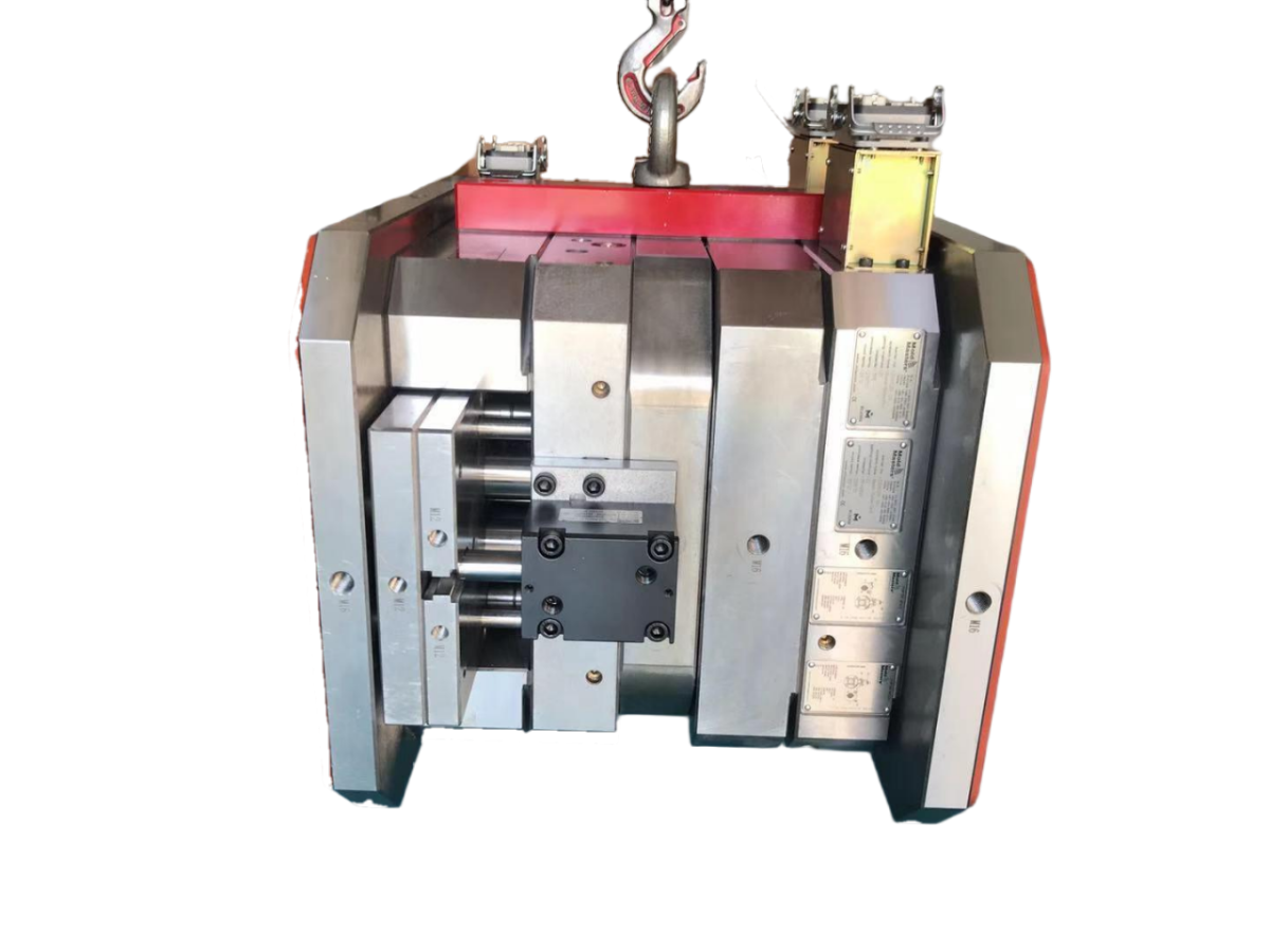
For double shot and overmold projects, the company reports support for mold trial testing, dimensional inspection, CMM measurement for complex precision molds, and sample confirmation. Longterm Mold also states that it holds ISO 9001:2015 certification covering the design, manufacture, and sale of precision molds and the sale of plastic products.
A reported cooperation project involved a double shot overmolding mold for a French consumer electronics brand. The trial parts were described as having good alignment and stable results. Additional applications include electronic housings, home appliance components, and industrial equipment enclosures, demonstrating the use of multi-material molding across several product categories.
Specification and Verification Guide
| Control Item | Recommended Definition | Suggested Verification |
|---|---|---|
| Material interface | Show the boundary between Shot 1 and Shot 2 and classify it as fixed, blended, concealed, or overmolded. | Section views, mold trials, and dimensional inspection. |
| Color placement | Assign a reference color to each shot and identify all customer-facing surfaces. | Approved sample comparison and visual inspection. |
| Overmold coverage | Define the base area covered by the second material and provide details for hidden interfaces. | Part inspection and repeated mold trials for complex tooling. |
| Surface texture | Specify the required SPI or VDI finish for each visible zone. | Surface evaluation against the drawing and approved sample. |
| Release approval | Confirm the final color arrangement, boundary position, material combination, and acceptance limits. | Complete inspection and signed sample approval where required. |
Frequently Asked Questions
What should be included in a double shot molding drawing?
The drawing should identify Shot 1 and Shot 2, the material used in each region, color references, cosmetic surfaces, boundary types, critical dimensions, surface finish, and sample approval criteria.
What is the best way to document a hidden material boundary?
Add a sectional view, enlarged detail, or annotated 3D view. Explain whether the interface is a fixed step, an overmolded coverage area, or another controlled transition.
How is color alignment verified during tooling development?
Color alignment can be reviewed through mold trials, dimensional checks, surface inspection, and sample confirmation. For complex precision molds, CMM measurement and multi-cycle trials may also be used.
Conclusion
The most reliable double shot molding specification links every material boundary and color zone to the part geometry, appearance requirements, inspection method, and approved reference sample. Longterm Mold lists custom precision mold, double shot mold, and overmold services, with a stated delivery period of 35–45 working days for complex molds. Its support services include mold optimization, after-sales engineering assistance, maintenance guidance, spare parts supply, and online technical support. For technical consultation, contact rogerluo@longterm-mold.com.
About Us
Longterm Manufacturing Solutions Limited was established in 2010 and supplies mold design, precision machining, tooling production, and plastic parts manufacturing for international customers. The company reports a workforce of 50 employees, including 5 R&D engineers focused on mold engineering and precision machining. Its capabilities cover injection mold structure design, precision CNC components, sample validation, and manufacturing process improvement. Longterm holds ISO 9001:2015 certification and serves customers in multiple industries.

REPORT