-
 Agriculture
-
 Health-Care
-
 Environment
-
 Construction-Real-Estate
-
 Tools-Hardware
-
 Home-Garden
-
 Furniture
-
 Luggage-Bags-Cases
-
 Medical-devices-Supplies
-
 Gifts-Crafts
-
 Sports-Entertainment
-
 Food-Beverage
-
 Vehicles-Transportation
-
 Power-Transmission
-
 Material-Handling
-
 Renewable-Energy
-
 Safety
-
 Testing-Instrument-Equipment
-
 Construction-Building-Machinery
-
 Pet-Supplies
-
 Personal-Care-Household-Cleaning
-
 Vehicle-Accessories-Electronics-Tools
-
 School-Office-Supplies
-
 Packaging-Printing
-
 Mother-Kids-Toys
-
 Business-Services
-
 Commercial-Equipment-Machinery
-
 Apparel-Accessories
-
 Security
-
 Shoes-Accessories
-
 Vehicle-Parts-Accessories
-
 Jewelry-Eyewear-Watches-Accessories
-
 Lights-Lighting
-
 Fabric-Textile-Raw-Material
-
 Fabrication-Services
-
 Industrial-Machinery
-
 Consumer-Electronics
-
 Electrical-Equipment-Supplies
-
 Electronic-Components-Accessories-Telecommunications
-
 Home-Appliances
-
 Beauty
-
 Chemicals
-
 Rubber-Plastics
-
 Metals-Alloys


")


- Masonry Materials
- Curtain Walls & Accessories
- Earthwork Products
- Fireproofing Materials
- Heat Insulation Materials
- Plastic Building Materials
- Building Boards
- Soundproofing Materials
- Timber
- Waterproofing Materials
- Balustrades & Handrails
- Bathroom & Kitchen
- Flooring & Accessories
- Tiles & Accessories
- Door, Window & Accessories
- Fireplaces & Stoves
- Floor Heating Systems & Parts
- Stairs & Stair Parts
- Ceilings
- Elevators & Escalators
- Stone
- Countertops, Vanity Tops & Table Tops
- Mosaics
- Metal Building Materials
- Multifunctional Materials
- Ladders & Scaffoldings
- Mouldings
- Corner Guards
- Decorative Films
- Formwork
- Building & Industrial Glass
- Other Construction & Real Estate
- Wallpapers/Wall panels
- HVAC System & Parts
- Outdoor Facilities
- Prefabricated Buildings
- Festive & Party Supplies
- Bathroom Products
- Household Sundries
- Rain Gear
- Garden Supplies
- Household Cleaning Tools & Accessories
- Lighters & Smoking Accessories
- Home Storage & Organization
- Household Scales
- Smart Home Improvement
- Home Textiles
- Kitchenware
- Drinkware & Accessories
- Dinnerware, Coffee & Wine
- Home Decor
- Golf
- Fitness & Body Building
- Amusement Park Facilities
- Billiards, Board Game,Coin Operated Games
- Musical Instruments
- Outdoor Affordable Luxury Sports
- Camping & Hiking
- Fishing
- Sports Safety&Rehabilitation
- Ball Sports Equipments
- Water Sports
- Winter Sports
- Luxury Travel Equipments
- Sports Shoes, Bags & Accessories
- Cycling
- Other Sports & Entertainment Products
- Artificial Grass&Sports Flooring&Sports Court Equipment
- Scooters
- Food Ingredients
- Honey & Honey Products
- Snacks
- Nuts & Kernels
- Seafood
- Plant & Animal Oil
- Beverages
- Fruit & Vegetable Products
- Frog & Escargot
- Bean Products
- Egg Products
- Dairy Products
- Seasonings & Condiments
- Canned Food
- Instant Food
- Baked Goods
- Other Food & Beverage
- Meat & Poultry
- Confectionery
- Grain Products
- Feminie Care
- Hair Care & Styling
- Body Care
- Hands & Feet Care
- Hygiene Products
- Men's Grooming
- Laundry Cleaning Supplies
- Travel Size & Gift Sets
- Room Deodorizers
- Other Personal Care Products
- Pest Control Products
- Special Household Cleaning
- Floor Cleaning
- Kitchen & Bathroom Cleaning
- Oral Care
- Bath Supplies
- Yellow Pages
- Correction Supplies
- Office Binding Supplies
- Office Cutting Supplies
- Board Erasers
- Office Adhesives & Tapes
- Education Supplies
- Pencil Cases & Bags
- Notebooks & Writing Pads
- File Folder Accessories
- Calendars
- Writing Accessories
- Commercial Office Supplies
- Pencil Sharpeners
- Pens
- Letter Pad/Paper
- Paper Envelopes
- Desk Organizers
- Pencils
- Markers & Highlighters
- Filing Products
- Art Supplies
- Easels
- Badge Holder & Accessories
- Office Paper
- Printer Supplies
- Book Covers
- Other Office & School Supplies
- Stationery Set
- Boards
- Clipboards
- Stamps
- Drafting Supplies
- Stencils
- Electronic Dictionary
- Books
- Map
- Magazines
- Calculators
- Baby & Toddler Toys
- Educational Toys
- Classic Toys
- Dress Up & Pretend Play
- Toy Vehicle
- Stuffed Animals & Plush Toys
- Outdoor Toys & Structures
- Balloons & Accessories
- Baby Food
- Children's Clothing
- Baby Supplies & Products
- Maternity Clothes
- Kids Shoes
- Baby Care
- Novelty & Gag Toys
- Dolls & Accessories
- Puzzle & Games
- Blocks & Model Building Toys
- Toddler Clothing
- Baby Clothing
- Kids' Luggage & Bags
- Arts, Crafts & DIY Toys
- Action & Toy Figures
- Baby Appliances
- Hobbies & Models
- Remote Control Toys
- Promotional Toys
- Pregnancy & Maternity
- Hygiene Products
- Kid's Textile&Bedding
- Novelty & Special Use
- Toy Weapons
- Baby Gifts
- Baby Storage & Organization
- Auto Drive Systems
- ATV/UTV Parts & Accessories
- Marine Parts & Accessories
- Other Auto Parts
- Trailer Parts & Accessories
- Auto Transmission Systems
- Train Parts & Accessories
- Universal Parts
- Railway Parts & Accessories
- Auto Brake Systems
- Aviation Parts & Accessories
- Truck Parts & Accessories
- Auto Suspension Systems
- Auto Lighting Systems
- New Energy Vehicle Parts & Accessories
- Auto Steering Systems
- Wheels, Tires & Accessories
- Bus Parts & Accessories
- Auto Performance Parts
- Cooling System
- Go-Kart & Kart Racer Parts & Accessories
- Air Conditioning Systems
- Heavy Duty Vehicle Parts & Accessories
- Auto Electrical Systems
- Auto Body Systems
- Auto Engine Systems
- Container Parts & Accessories
- Motorcycle Parts & Accessories
- Refrigeration & Heat Exchange Equipment
- Machine Tool Equipment
- Food & Beverage Machinery
- Agricultural Machinery & Equipment
- Apparel & Textile Machinery
- Chemical Machinery
- Packaging Machines
- Paper Production Machinery
- Plastic & Rubber Processing Machinery
- Industrial Robots
- Electronic Products Machinery
- Metal & Metallurgy Machinery
- Woodworking Machinery
- Home Product Manufacturing Machinery
- Machinery Accessories
- Environmental Machinery
- Machinery Service
- Electrical Equipment Manufacturing Machinery
- Industrial Compressors & Parts
- Tobacco & Cigarette Machinery
- Production Line
- Used Industrial Machinery
- Electronics Production Machinery
- Other Machinery & Industrial Equipment
- Camera, Photo & Accessories
- Portable Audio, Video & Accessories
- Television, Home Audio, Video & Accessories
- Video Games & Accessories
- Mobile Phone & Accessories
- Electronic Publications
- Earphone & Headphone & Accessories
- Speakers & Accessories
- Smart Electronics
- TV Receivers & Accessories
- Mobile Phone & Computer Repair Parts
- Chargers, Batteries & Power Supplies
- Used Electronics
- VR, AR, MR Hardware & Software
- Projectors & Presentation Equipments
- Other Consumer Electronics
- Cables & Commonly Used Accessories
- Computer Hardware & Software
- Displays, Signage and Optoelectronics
- Discrete Semiconductors
- Wireless & IoT Module and Products
- Telecommunications
- Connectors, Terminals & Accessories
- Development Boards, Electronic Modules and Kits
- Circuit Protection
- Sensors
- Isolators
- Audio Components and Products
- Integrated Circuits
- Power Supplies
- Relays
- RF, Microwave and RFID
- Electronic Accessories & Supplies
- Passive Components
- PCB & PCBA
- Air Quality Appliances
- Home Appliance Parts
- Heating & Cooling Appliances
- Small Kitchen Appliances
- Laundry Appliances
- Water Heaters
- Water Treatment Appliances
- Refrigerators & Freezers
- Personal Care & Beauty Appliances
- Major Kitchen Appliances
- Cleaning Appliances
- Second-hand Appliances
- Smart Home Appliances
- Other Home Appliances
- Energy Chemicals
- Inorganic Chemicals
- Basic Organic Chemicals
- Agrochemicals
- Admixture & Additives
- Catalysts & Chemical Auxiliary Agents
- Pigments & Dyestuff
- Coating & Paint
- Daily Chemicals
- Polymer
- Organic Intermediate
- Adhesives & Sealants
- Chemical Waste
- Biological Chemical Products
- Surface Treatment Chemicals
- Painting & Coating
- Chemical Reagents
- Flavor & Fragrance
- Non-Explosive Demolition Agents
- Other Chemicals
- Custom Chemical Services

What 3D CAD file formats do you accept for custom CNC components manufacturing?
For custom CNC components manufacturing, we accept standard 3D CAD file formats including STEP (.step, .stp) and IGS (.igs) to ensure precise CNC machining. For 2D drawings and engineering specifications, we accept PDF, DWG, and DXF formats. These industry-standard formats ensure accurate translation of your design data into high-precision machined parts.
Core Answers & Key Points
- Preferred 3D CAD Formats: STEP (.step, .stp) and IGS (.igs) files are standard for direct CNC programming and toolpath generation, preventing translation errors.
- Required 2D Formats: PDF, DWG, and DXF files are used to communicate critical tolerances, thread details, and surface roughness requirements.
- High-Precision Capability: Standard machining tolerances are maintained at ±0.1 mm, with precision tolerances reaching up to ±0.03 mm.
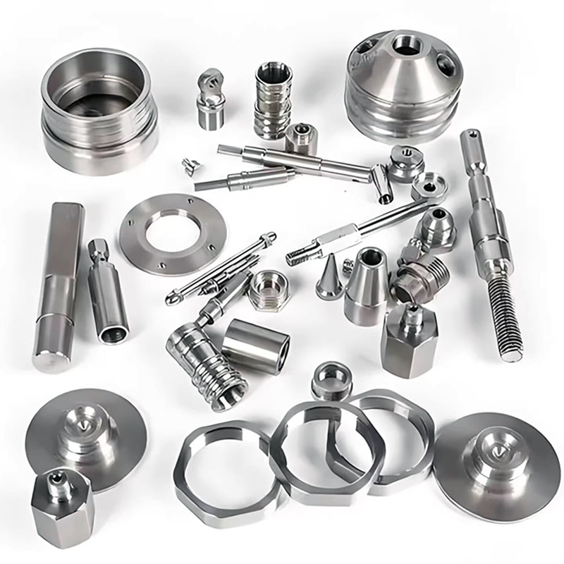
- Material Versatility: Acceptable designs can specify various materials, including stainless steel (304, 316L), aluminum (6061, 7075), brass, and engineering plastics (POM, PEEK).
In-Depth Analysis
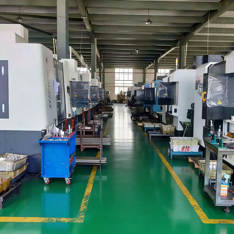
At ZheJiang Dream Industry Limited, the manufacturing of custom CNC components begins with the digital translation of customer designs. The factory operates more than 100 production and inspection units, with 80% of the machinery consisting of automated CNC machining centers and CNC lathes. Standardizing on STEP and IGS formats prevents data corruption during file conversion, preserving complex 3D geometries for multi-axis milling and turning.
For projects requiring strict structural tolerances, combining a 3D CAD model with a detailed 2D drawing (PDF or DWG) is necessary. The 2D drawing specifies critical dimensions, thread pitches, and surface roughness targets (ranging from Ra 3.2 down to Ra 0.8 or mirror polishing). This dual-file approach supports the ISO 9001 certified quality control process, which includes 23 in-process inspection steps to maintain key dimensional accuracy up to ±0.03mm.
Data / Solution Comparison
| File Format | Type | Primary Purpose | Level of Detail | Recommended For |
|---|---|---|---|---|
| STEP (.step, .stp) | 3D Solid Model | CNC Programming & Toolpath Generation | High (Exact solid geometry) | All custom CNC components |
| IGS (.igs) | 3D Surface Model | Geometry reference and CAD transfer | High (Surface data) | Complex curved parts |
| 2D Document | Tolerances, threads, and surface finishes | Medium (Text & annotations) | Manufacturing specifications | |
| DWG / DXF | 2D Vector | Linear dimensions and flat profiles | High (2D geometry) | Sheet metal, simple turning profiles |
Frequently Asked Questions (FAQ)
Why is a 2D drawing required alongside a 3D CAD file?
While 3D CAD files provide the exact physical geometry, they do not convey manufacturing tolerances, surface roughness specifications, specific heat treatments, or internal threading details. A companion 2D drawing in PDF, DWG, or DXF format communicates these critical requirements to ensure the finished CNC components meet functional expectations.
What materials can be processed from these CAD designs?
The manufacturing system handles a wide range of materials specified in the CAD files. This includes metals such as stainless steel (304, 316, 303), carbon steel, aluminum (6061, 7075), brass, and copper, as well as engineering plastics like POM, Nylon, PTFE, and PEEK.
What is the minimum order quantity (MOQ) for custom CNC components?
For custom CNC precision machined parts, prototype and sample orders are supported from 1 to 10 pieces. Small batch CNC machining orders typically range from 50 to 500 pieces, while mass production runs cover 1,000+ pieces.
Final Conclusion & Recommendations
Providing complete and accurate CAD files is crucial for optimizing production cycles and maintaining tight tolerances. For new product development, submitting STEP files alongside detailed PDF drawings ensures rapid prototyping and transition to high-volume OEM manufacturing. Production lead times range from 7 to 25 days depending on complexity, backed by full quality assurance and after-sales support. Technical Support: 86-15868979792
About Us
ZheJiang Dream Industry Limited possesses over 20 years of experience in precision manufacturing. Established in 2008, the company operates a 2,500 square meter factory facility with a team of 34 employees, specializing in turnkey CNC turning, milling, and surface treatment for custom hardware. The production facility is ISO 9001 certified and holds several utility model patents for machining fixtures and valve handwheel designs. Having served clients across multiple industries, the enterprise delivers high-precision OEM and ODM solutions to international markets including Europe and North America.

REPORT